發表文章

目前顯示的是 2019的文章

How to use the USB3.0 camera from TheImagingSource

圖片
1. Install tiscamera.deb 2. Install dependencies as Dependencies link or as follows: git clone https://github.com/TheImagingSource/tiscamera.git cd tiscamera # Build dependencies sudo ./scripts/install-dependencies.sh --compilation --runtime # Runtime dependencies sudo ./scripts/install-dependencies.sh --runtime mkdir build cd build cmake -DBUILD_ARAVIS=OFF -DBUILD_GST_1_0=ON -DBUILD_TOOLS=ON -DBUILD_V4L2=ON -DCMAKE_INSTALL_PREFIX=/usr .. make sudo make install Test: 1. gst-launch-1.0 tcambin ! videoconvert ! ximagesink 2. tcam-capture *Needed library and head files: [4] Reference: [1]  https://github.com/TheImagingSource/tiscamera [2]  https://www.argocorp.com/cam/ImagingSource/Linux.html [3]  https://github.com/TheImagingSource/Linux-tiscamera-Programming-Samples [4]  https://github.com/TheImagingSource/tiscamera/blob/master/examples/c/Makefile

How to add user defined module in PX4

圖片
Step1: Create a ORB topic (~/Firmware/msg/) Step2: Add user defined topic in the CMakeList.txt (~/Firmware/msg/) Step3: Build the firmware [1] , and you will find a corresponding head file (~/Firmware/build/px4_fmu-v3_default/uORB/topics) Step4: Create user defined modules with CMakeLIst.txt and source code (~FIrmware/src/modules) Step5: Follow the px4_add_module.cmake to write your CMakeList.txt in Step4 Step6: FInd your board's default.cmake [2] Step7: Add your module name in the default.cmake (~Firmware/boards/px4/fmu-v3) Step8: build and upload your firmware [1] Step9-1: Test your function using QGroundCOntrol mavlink console Step9-2: Test your function using QGroundCOntrol mavlink console * The board I am using is Pixhawk2.1 cube. * You should have some background knowledge about PX4 uORB topic before doing these things. Reference: [1] Building PX4 Software [2] Flight Controller Configuration File Layouttml

Useful PX4 Parameters

1. For setting companion link SYS_COMPANION (Before ver. 1.9.0) MAV_0_CONFIG, MAV_0_MODE (After ver. 1.9.0) 2. EKF2 configuration EKF2_AID_MASK EKF2_HGT_MODE EKF2_EV_DELAY (Reduce this parameter if high rate external vision is available) EKF2_EV_POS_X, EKF2_EV_POS_Y, EKF2_EV_POS_Z 3. Offboard mode parameters ( The vehicle will exit the mode if target setpoints are not received at a rate of > 2Hz ) COM_OBL_RC_ACT (Default: position mode, I set land mode) COM_OBL_ACT COM_OF_LOSS_T 4. Position loss failsafe COM_POSCTL_NAVL 5. Land mode MPC_LAND_SPEED COM_DISARM_LAND: Time-out for auto disarm after landing. (Default: 0, I set 3.) 6. TBD Reference: [1]  https://dev.px4.io/en/advanced/parameter_reference.html [2]  https://dev.px4.io/en/ros/external_position_estimation.html#tuning-EKF2_EV_DELAY [3]  https://docs.px4.io/en/config/safety.html#qgc_safety_setup

Further setup and tuning for a high-speed drone

圖片
Configuration:  The minimal configuration is to use only a gyro and accelerometer sensor. Considering the  electromagnetic interference, disable the magnetometer . Make sure to balance the propellers . [2] Make sure that the center of gravity is as close as possible to the center of thrust . Choose Generic 250 Racer airframe in QGC. Switch the estimator to local_position_estimator if no external position available. (ex: GPS, camera, etc.) Make sure to calibrate the ESCs. Control latency: Enable SYS_FMU_TASK to reduce latency. Disable SYS_USE_IO and attach the motors to the AUX pins instead. Enable One-Shot PWM output signal to reduce latency ( PWM_RATE =0) Filter tuning: Tune the low-pass filter on the gyro sensor data:  IMU_GYRO_CUTOFF . Tune the low-pass filter on the D-term:  MC_DTERM_CUTOFF . Step1: Active  high-rate logging profile ( SDLOG_PROFILE  parameter) Step2: T une the gyro filter  IMU_GYRO_CUTOFF  by increasing it in steps of 10 Hz

Advanced parameters tuning for evaluating the control performance

圖片
Definition: The PX4 position controller  consists of an outer   P   position-control loop and an inner   PID  velocity-control loop as shown in the following figure.  Usually in PX4,   position-control  represents the case where both loops are active while  velocity-control  refers to the case when only the velocity control loop is in use. Multicopter position controller [1] Here are some parameters you can set for realizing better control performance [3]. Make sure you have finished the basic PID tuning before tuning the parameters mentioned in this article. MPC_HOLD_DZ:   Deadzone of sticks where position hold is enabled. MPC_ACC_HOR_MAX :   Maximum horizontal acceleration for auto mode and for manual mode. MPC_ACC_HOR:  Acceleration for auto and for manual. MPC_DEC_HOR_SLOW:  Slow horizontal manual deceleration for manual mode. MPC_ACC_UP_MAX:  Maximum vertical acceleration in velocity controlled modes upward. MPC_ACC_DOWN_MAX:  Maximum vertical acceleration

Tuing PID parameters in QGroundcontrol (2)

圖片
Based on tips for tuning PX4 PID parameters written in my previous post [1] or even using the default values directly, you will be able to fly your vehicle freely in manual or stabilized flight mode.   However, if you are using an unique vehicle (usually assembly by yourself and only equipped with sensors you desire) and struggling for finding the best PID parameters for your applications. I think following 8 tips will help you to get ideal PID parameters.  This is the vehicle I made based on LHI QAV250 fiber frame, with TX2, high-speed camera, etc.[2]  Tip1:  Tuning order: Rate controller -> attitude controller -> position controller The PX4 controllers are layered [3], which means a higher-level controller passes its results to a lower-level controller. Thus the PID tuning needs to be done from lowest-level controller to highest-level controller. Tip2:  Check if  PWM_MIN  is set correctly. Remove propellers Arm the vehicle and lower the throttle to the minimu

Making a open source quadrotor using LHI QAV250 frame (2)

圖片
3. Calibration using QGroundControl Connection using USB cable Firmware setup Frame setting : QAV250 Radio calibration   Flight mode setting Battery setting ESC calibration ENJOY YOUR FLIGHT WITH DEFAULT PARAMETERS!

Making a open source quadrotor using LHI QAV250 frame (1)

圖片
1. Main materials LHI QAV250 Carbon Fiber Frame MT2204 brushless motor *4 Simonk 12A ESC *4 Flight controller: Pixhawk 2.1 5030 propeller pairs *2 Lipo battery: 2200mAh 35C Radio receiver: Spectrum  DSMX quad race receiver 2. Assembly Motors with connectors + legs Power distribution board + ESCs Motors + Power distribution board + ESCs + body + propeller + battery + flight controller (Check if the rotation direction is correct!)

Making a open source quadrotor using DJI 450 frame

圖片
1. Main materials Quadcopter frame: F450 HJ450 DJI Four sets of Motors and ESC: A2212 1000KV (brushless motor), 30A ESC Bullet connector: 3.5mm Four pairs of propellers: 1045 Flight controller: Pixhawk2.1 standard set RC receiver-transmitter set: Spektrum DSMX quad race receiver with diversity [Optional] Landing gear 2. Assembly Frame Power distribution for motors Motor & ESC connector Overall power distribution: for a pixhawk2.1, Jetson TX2, and motors. (A 4cells Lipo battery with 4000mAh is chosen in my case) Assembly result: basic requirements Reference: [1]  http://ardupilot.org/copter/docs/connect-escs-and-motors.html

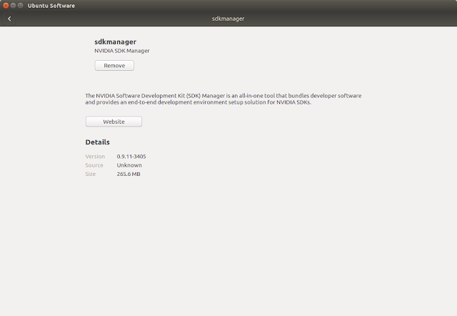
NVIDIA SDK Manager

圖片
This article shows how to use NVIDIA SDK Manager as using Jetpack series. Step1: Download sdkmanager [1]  Step2: Log in and select your installing options.   Step3: Wait for the download completed.  Step4: Setting connection between device and your PC, and then start flashing your device.  Step5: Follow the instruction shown on the window to complete the system configuration of your device and then login in.  Step6: Continue the rest installation.  *If you have trouble while installing OpenCV like me, try to install libpython2.7-dev on your target manually, and restart the installation process, you should be good to go!  Failed to install libpython2.7 Click the link in the terminal, and install libpython2.7-dev by yourself.   Completed! *Optional: Build OpenCV with CUDA support from source. [2] [3] *Optional: If you are using a carrier board, don't forget to install their driver. ex: [4-5] *Check your L4T version. [6]